

| Place of Origin: | SZ China |
|---|---|
| Brand Name: | OLKOPTO |
| Certification: | ISO9001,ISO14001,OHSAS18001 |
| Model Number: | OLCF85TXMX-CDS1 |
| Minimum Order Quantity: | 1pcs |
| Packaging Details: | Individual package OR 10 pcs/ pallet OR 20 pcs/ pallet |
| Delivery Time: | 3-5 working days |
| Payment Terms: | TT/Net 30days |
| Supply Ability: | 80-100k per month |
| Part Number: | OLCF85TXMX-CDS1 | Data Rate: | 100G |
|---|---|---|---|
| Wavelength: | 850nm | Transmission Distance: | 100m |
| Highlight: | 100G QSFP Optical Module,SR10 QSFP Optical Module,100m qsfp28 100g |
||
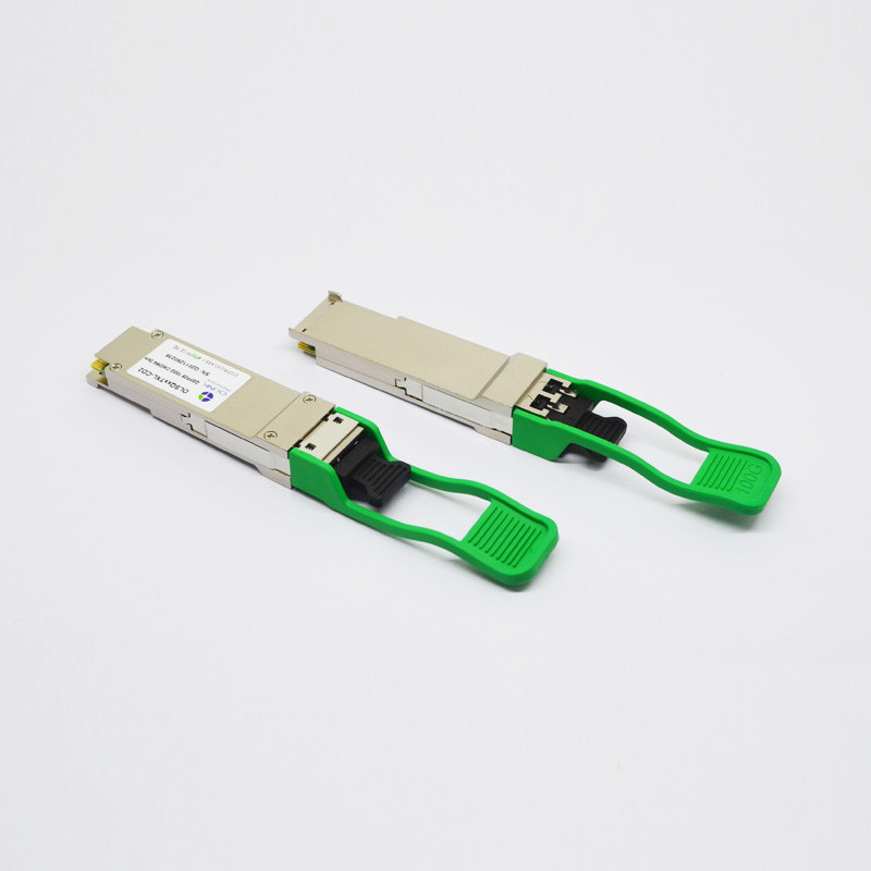
Cisco Compatible 100G QSFP28 Optical Module CFP2 SR10 850nm 100m LC MMF
Cisco Compatible QSFP 28 100G CFP2 SR10 850nm 100m LC MMF Optical Transceiver Module
Product Features
● Supports 103.1Gb/s to 112Gb/s bit rates
● MPO 24 receptacle optical interface
● CPPI electrical interface
● Uncooled 10x10Gb/s 850nm transmitter
● 10 parallel electrical serial interface
● Applicable for 100m with OM3 MMF and 150m with OM4 MMF
● Low power consumption <4W
● Digital Diagnostic Monitor Interfacel ●MDIO Communication Interface
● Compliant with 100GBASE-SR10
● Operating case temperature:
Commerical:0 to 70 °C
Applications
● 100GBASE-SR10 Ethernet
● 10x11.2Gb/s Multimode OTN
● 10x 10GE-SRLite Ethernet
Standards
● Compliant with IEEE 802.3ba
● Compliant with CFP2 MSA hardware specifications
● Compliant with CFP2 MSA management specifications
Functional Description
Olinkcom’s OLCF85TXMX-CDS1, the 100GE SR10 CFP2 (ALT1) transceiver modules are designed for use in 100 Gigabit Ethernet links and 10x11.2G OTN client interfaces over multimode fiber. They are compliant with the CFP2 MSA and with IEEE 802.3ba 100GBASE-SR10. Digital diagnostics functions are available via the MDIO interface.
Optical Characteristics (TOP = 0 to 70 °C, VCC = 3.13 to 3.47 V)
| Parameter | Symbol | Min. | Typ | Max. | Unit | Note |
| Transmitter (per Lane) | ||||||
| Data Rate Per Lane | DRPL | 10.3125 | 11.1810 | Gb/s | 1 | |
| Center wavelength | λ | 840 | 850 | 860 | nm | |
| RMS Spectral Width | Δλ | 0.65 | nm | |||
| Average Power per Lane | PAVEp | -8 | 1 | dBm | ||
| Transmit OMA per Lane | POMA | -6 | 3.0 | dBm | 2 | |
| Average launch Power of OFF | DP | -30 | dB | |||
| Peak Power per Lane | PP | 4.0 | dBm | |||
| TDP per Lane | TDP | 4 | dBm | |||
| Extinction Ratio | ER | 3.0 | dB | |||
| Return Loss Tolerance | 12 | dB | ||||
| Relative Intensity Noise | RIN | -128 | dB/Hz | 3 | ||
| Transmitter eye mask definition {X1, X2, X3, Y1, Y2, Y3} | 0.23, 0.34, 0.43, 0.27, 0.35, 0.4 | |||||
| Receiver (per Lane) | ||||||
| Center wavelength | λ | 840 | 850 | 860 | nm | |
| Receiver Sensitivity per Lane | PSEN1 | -9.9 | dBm | 4 | ||
| Receiver Sensitivity (OMA) per Lane | PSEN2 | -5.4 | dBm | |||
|
Peak Power, per lane
|
PPx | 4 | dBm | |||
| Overload,perlane | PAVE | 1 | dBm | |||
|
Receiver Reflectance
|
Rrx | -12 | dB | |||
|
Dispersion penalty , per lane
|
TDP | 1.9 | dB | |||
|
Stressed eye J2 jitter, per Lane
|
JE2P | 0.35 | UI | |||
|
Stressed eye J9 jitter, per Lane
|
JE9P | 0.47 | UI | |||
|
Jitter tolerance [OMA], per lane
|
JTP | -5.4 | dBm | |||
|
LOS De-Assert
|
Pa | -11 | dBm | |||
|
LOS Assert
|
Pd | -25 | dBm | |||
|
LOS Hysteresis
|
Pd-Pa | 0.5 | dB | |||
Notes:
1. Transmitter consists of 10 lasers operating at a maximum rate of 11.1810 Gb/s each.
2. Even if TDP is <0.9dB, the OMA min must exceed this value.
3. RIN is scaled by 10*log (10/4) to maintain SNR outside of transmitter.
4. Measured using DUT Tx and DUT Rx; no golden transmitters shall be used.
More details of our products:
High Reliable Optical Components and Excellent Design
1.DLB laser and PIN photodiode
2.Thick Gold Finger
3.Plating Hard Gold Shell
Cost-effective and Reliable Transmission
Our Packing & Labeling:
Our all modules have 3 years warranty!


