

| Place of Origin: | Shenzhen China |
|---|---|
| Brand Name: | OLKOPTO |
| Certification: | RoHS FCC CE GS UL FDA etc |
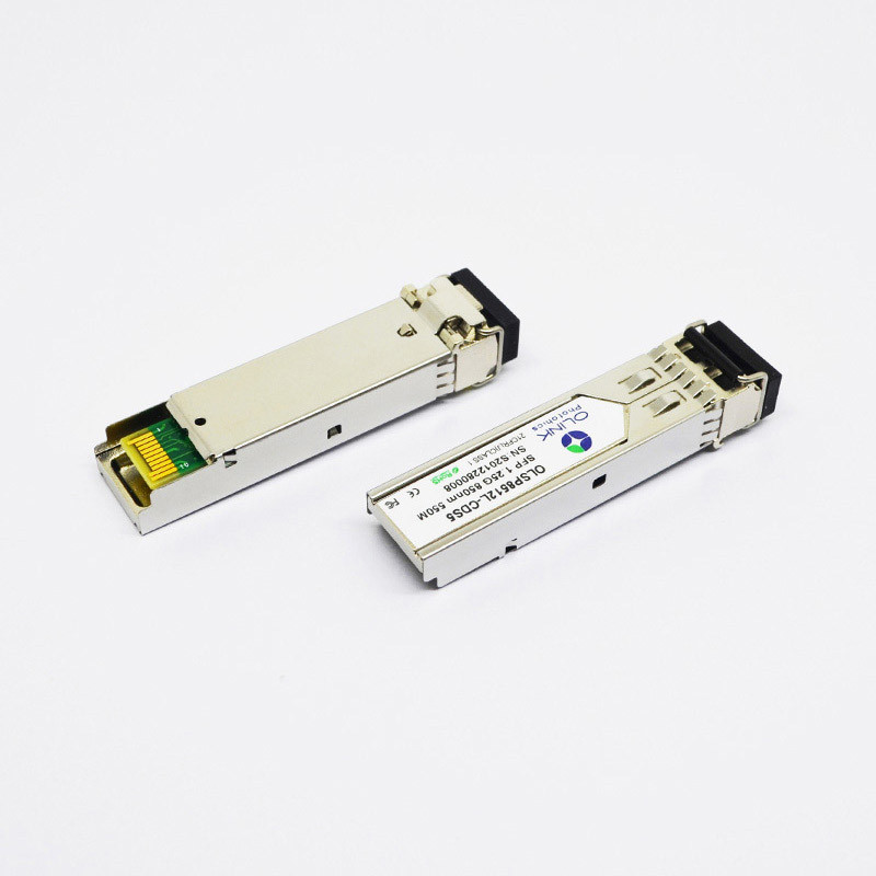
| Model Number: | OLSP8512L-CDS5 |
| Minimum Order Quantity: | 1pc |
| Packaging Details: | Individual package Or 10pcs/pallet Or 20pcs/pallet |
| Delivery Time: | 3-5 working days |
| Payment Terms: | T/T or Net 30 days |
| Supply Ability: | 80-120k per month |
| Form Factor: | SFP | Data Rate: | 1.25Gbps/1.0625Gbps |
|---|---|---|---|
| Compatibility: | Extreme | Wavelength: | 850nm |
| Distance: | 550m | Connector: | LC Duplex |
| DDM/DOM: | Supported | Fiber Type: | MMF |
| Commercial Temperature Range: | 0 To 70 °C | Industrial Temperature Range: | -40 To 85 °C |
| Highlight: | 550m Fiber Optic Transceiver,3.3V Fiber Optic Transceiver,550m 1000base sfp |
||
Extreme Compatible SFP Fiber Optic Transceiver 1000BASE-SX 850nm 550m
SFP Optical Transceiver Extreme Compatible 1000BASE-SX SFP 850nm 550m Module
Product Features
Olinkcom's OLSP8512L-CDS5 is hot pluggable 3.3V Small-Form-Factor transceiver module. It designed expressly for high-speed communication applications that require rates up to 11.3Gb/s, it designed to be compliant with XFP MSA. The module data link up to 40km in 9/125um single mode fiber.
Pin Defintion And Functions
| Pin | Symbol | Name/Description | Notes |
| 1 | VeeT | Tx ground | |
| 2 | Tx Fault | Tx fault indication, Open Collector Output, active “H” | 1 |
| 3 | Tx Disable | LVTTL Input, internal pull-up, Tx disabled on “H” | 2 |
| 4 | MOD-DEF2 | 2 wire serial interface data input/output (SDA) | 3 |
| 5 | MOD-DEF1 | 2 wire serial interface clock input (SCL) | 3 |
| 6 | MOD-DEF0 | Model present indication | 3 |
| 7 | Rate select | No connection | |
| 8 | LOS | Rx loss of signal, Open Collector Output, active “H” | 4 |
| 9 | VeeR | Rx ground | |
| 10 | VeeR | Rx ground | |
| 11 | VeeR | Rx ground | |
| 12 | RD- | Inverse received data out | 5 |
| 13 | RD+ | Received data out | 5 |
| 14 | VeeR | Rx ground | |
| 15 | VccR | Rx power supply | |
| 16 | VccT | Tx power supply | |
| 17 | VeeT | Tx ground | |
| 18 | TD+ | Transmit data in | 6 |
| 19 | TD- | Inverse transmit data in | 6 |
| 20 | VeeT | Tx ground |
Notes:
1. When high, this output indicates a laser fault of some kind. Low indicates normal operation. And should be pulled up with a 4.7 – 10KΩ resistor on the host board.
2. TX disable is an input that is used to shut down the transmitter optical output. It is pulled up within the module with a 4.7 – 10KΩ resistor. Its states are:
Low (0 – 0.8V): Transmitter on (>0.8, < 2.0V): Undefined
High (2.0V~Vcc+0.3V): Transmitter Disabled Open: Transmitter Disabled
3. Mod-Def 0,1,2. These are the module definition pins. They should be pulled up with a 4.7K – 10KΩ resistor on the host board. The pull-up voltage shall be between 2.0V~Vcc+0.3V.
Mod-Def 0 has been grounded by the module to indicate that the module is present
Mod-Def 1 is the clock line of two wire serial interface for serial ID
Mod-Def 2 is the data line of two wire serial interface for serial ID
4. When high, this output indicates loss of signal (LOS). Low indicates normal operation.
5. RD+/-: These are the differential receiver outputs. They are AC coupled 100Ω differential lines which should be terminated with 100Ω (differential) at the user SERDES. The AC coupling is done inside the module and is thus not required on the host board.
6. TD+/-: These are the differential transmitter inputs. They are AC-coupled, differential lines with 100Ω differential termination inside the module. The AC coupling is done inside the module and is thus not required on the host board.
Applications
● Gigabit Ethernet
● Fiber Channel
● Switch to Switch interface
● Switched backplane applications
● Router/Server interface
● Other optical transmission systems
Ordering Information
| Part Number | Description |
| OLSP8512L-CDS5 | SFP,1.25Gbps, 850nm, Multimode,550m, 0~70℃, with Digital Diagnostic Monitor |
| OLSP8512L-IDS5 | SFP,1.25Gbps, 850nm, Multimode,550m, -40~85℃, with Digital Diagnostic Monitor |


