

| Place of Origin: | SZ China |
|---|---|
| Brand Name: | OLKOPTO |
| Certification: | ISO9001,ISO14001,OHSAS18001 |
| Model Number: | OLCFXXTXL-CD40 |
| Minimum Order Quantity: | 1pcs |
| Packaging Details: | Individual package OR 10 pcs/ pallet OR 20 pcs/ pallet |
| Delivery Time: | 3-5 working days |
| Payment Terms: | TT/Net 30days |
| Supply Ability: | 80-100k per month |
| Part Number: | OLCFXXTXL-CD40 | Data Rate: | 100G |
|---|---|---|---|
| Compitible Brand: | Generic,Cisco,Juniper,MikroTik | Form Factor: | CFP2 |
| Connector: | LC | Power Consumption: | < 12W |
| Highlight: | 100GBASE-ER4 CFP2 Optical Transceiver,Juniper Compatible CFP2 Optical Transceiver,40km CFP2 Optical Transceiver Module |
||
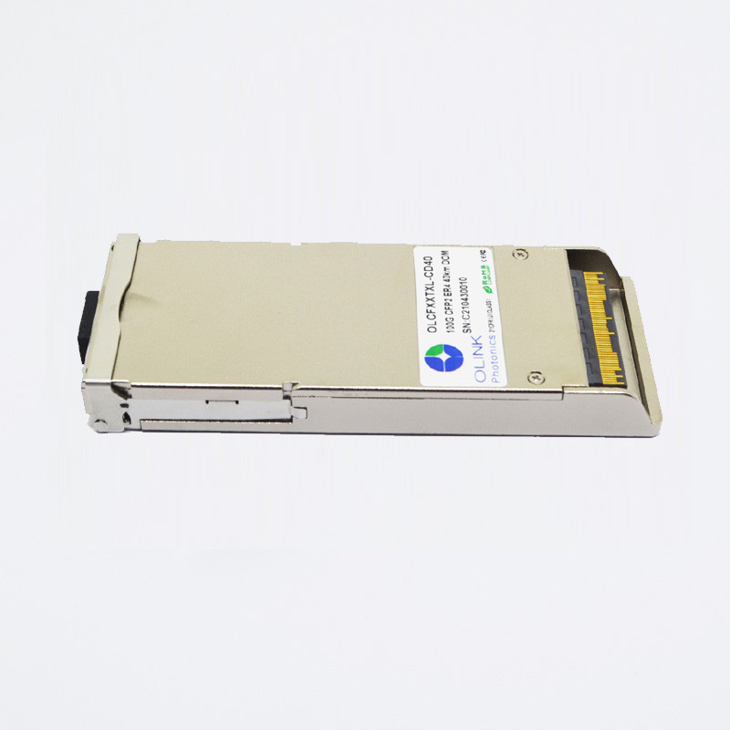
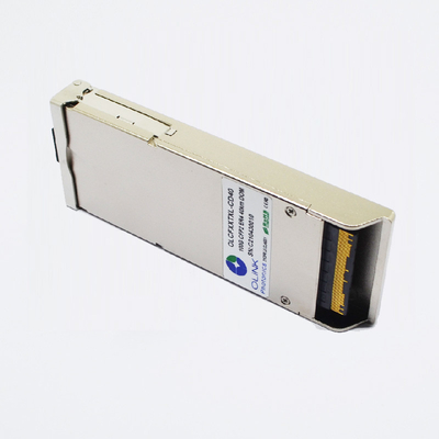
100G CFP2 ER4 40km Optical Transceiver Modules Compatible With Juniper
RoHS Compliant 100Gb/s CFP2 ER4 40km Optical Transceiver
Product Features
● Supports up to 112Gbps bit rates
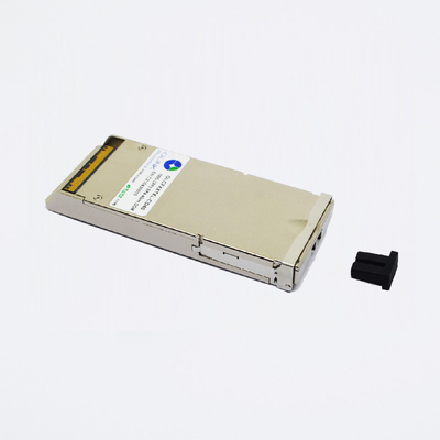
● Duplex LC connector
● Hot pluggable
● Operating electrical serial data rate up to 27.952493Gbps
● APD ROSA
● 4 parallel electrical serial interface
● Applicable for 30km SMF connection
● Low power consumption, < 12W
● Digital Diagnostic Monitor Interfacel
● MDIO Communication Interface
● Compliant with 100GBASE-ER4
● Operating case temperature:
Commerical:0 to 70 °C
Applications
● Local Area Network(LAN)
● Wide Area Network(WAN)
● Switch to router interface
Standards
● Compliant with IEEE 802.3ba
● Compliant with CFP2 MSA hardware specifications
● Compliant with CFP2 MSA management specifications
● Compliant with ITU-T G709/Y.1331
● Compliant with RoHS
Functional Description
Olinkphotonics’ OLCFXXTXL-CD40, The 100G CFP2 ER4 optical transceiver integrates the transmit and receive path onto one module. On the transmit side, four lanes of serial data streams are recovered, retimed,and passed on to four laser drivers, which control four electric-absorption modulated lasers (EMLs) with 1296, 1300, 1305, and 1309 nm center wavelengths. The optical signals are then multiplexed into a single-mode fiber through an industry-standard LC connector.On the receive side, four lanes of optical data streams are optically demultiplexed by an integrated optical demultiplexer. Each data steam is recovered by a PIN photodetector and transimpedance amplifier, retimed, and passed on to an output driver. This module features a hot-pluggable electrical interface, low power consumption, and MDIO management interface.
Optical Characteristics
(Tested under recommended operating conditions,unless otherwise noted)
| Parameter | Symbol | Unit | Min | Typ | Max | Notes | |||||
| Optical Transmitter Characteristics | |||||||||||
| Signaling rate, each lane | GBd | 25.78125 ±100 ppm | 100GBase-ER4 | ||||||||
| 27.9525 ±20 ppm | OTU4 | ||||||||||
| Four Lane Wavelength Range | λ1 | nm | 1294.53 | 1295.56 | 1296.59 | ||||||
| λ2 | 1299.02 | 1300.05 | 1301.09 | ||||||||
| λ3 | 1303.54 | 1304.58 | 1305.63 | ||||||||
| λ4 | 1308.09 | 1309.14 | 1310.19 | ||||||||
| Total launch power | dBm | 8.9 | 100GBase-ER4 | ||||||||
| Average launch power, each lane | Pavg | dBm | -2.9 | 2.9 | 2 | ||||||
| Optical modulation amplitude, each lane (OMA)2 | OMA | dBm | 0.1 | 4.5 | |||||||
| Difference in launch power between any two lanes (OMA) | dB | 3.6 | |||||||||
| Extinction ratio | ER | dB | 8 | 100GBase-ER4 | |||||||
| Side-mode suppression ratio | SMSR | dB | 30 | ||||||||
| Transmitter and dispersion penalty, each lane | TDP | dB | 2.5 | ||||||||
| Optical return loss tolerance | dB | 20 | |||||||||
| Transmitter reflectance3 | dB | –12 | |||||||||
| Transmitter eye mask {X1, X2, X3, Y1, Y2, Y3} | {0.25, 0.4, 0.45, 0.25, 0.28, 0.4} | 100GBase-ER4 | |||||||||
| Optical Receiver Characteristics | |||||||||||
| Receive Rate for Each Lane | Gbps | 25.78125 | 27.9525 | ||||||||
| Overload Input Optical Power | Pmax | dBm | 5.5 | 3 | |||||||
|
Average Receive Power for Each Lane |
Pin | dBm | -20.9 | 4.5 | 4, 5 | ||||||
|
Receive Power In OMA for Each Lane |
PinOMA | dBm | 4.5 | ||||||||
|
Difference in Receive Power in OMA between Any Two Lanes |
dBm | 4.5 | |||||||||
|
Receiver Sensitivity in OMA for Each Lane |
SOMA | dBm | -21.4 | 6 | |||||||
|
Stressed Receiver Sensitivity in OMA for Each Lane |
dBm | -17.9 | 7, 8 | ||||||||
Notes:
1. The supply current includes CFP2 module’s supply current and test board workingcurrent.
2. Average launch power, each lane (min) is informative for 100GBase-LR4, not the principal indicator of signal strength.
3. The receiver shall be able to tolerate , without damage, continuous exposure to an optical input signal having this average power level
4. The average receive power , each lane (max) for 100GBASE-ER4 is larger than the 100BASE-ER4 transmitter value to allow compatibility with 100BASE-LR4 units at short distances
5. Average receive power, each lane (min) is informative and not the principal indicator
of signal strength. A received power below this value cannot be compliant; however, a value above this does not ensure compliance
6. Receiver sensitivity (OMA), each lane (max) is informative
7. Measured with conformance test signal at TP3 for BER=10-12
8. conditions of stressed receiver sensitivity test: vertical eye closure penalty for each lane is 1.8dB;stressed eye J2 jitter for each lane is 0.3UI; stressed eye J9 jitter for each lane is 0.47UI.
More details of our products:
High Reliable Optical Components and Excellent Design
1. DLB laser and PIN photodiode
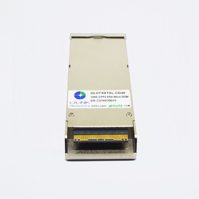
2. Thick Gold Finger
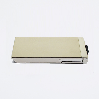
3. Plating Hard Gold Shell
Cost-effective and Reliable Transmission
Our Packing & Labeling:
Our all modules have 3 years warranty!

